1998 F250 Engine Fuse Box Panel Diagram
Ford F250, F350, F450, F550 – fuse and relay
Ford F-Series Super Duty includes a lineup Ford F250, F350, F450, F550. In this publication we will show a designation of fuses and relays Ford F250, F350, F450, F550 produced in 2011, 2012, 2013, 2014, 2015, 2016 with box diagrams and their locations. Highlight the cigarette lighter fuse.

The execution of the boxes may differ from that shown. Include the purpose with your technical documentation.
Passenger compartment fuse box
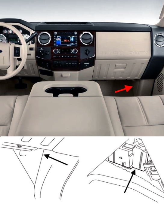
The fuse box is located in the passenger's footwell. To remove the fuse panel cover, pull the panel toward you. When the clips of the panel disengage, let the panel fall easily.
Diagram

Assignment
| 1 | 30A – (spare) |
| 2 | 15A Upfitter relay #4 |
| 3 | 30A Passenger smart window motor |
| 4 | 10A Telescoping mirror switch, Interior lights, Hood lamp |
| 5 | 20A Sunroof |
| 6 | 5A Driver seat module |
| 7 | 7,5A Driver seat switch, Driver lumbar motor |
| 8 | 10A Power mirror switch |
| 9 | 10A Upfitter relay #3 |
| 10 | 10A Run/accessory relay, Customer access feed |
| 11 | 10A Instrument cluster |
| 12 | 15A Interior lighting, Lighted running board lamps |
| 13 | 15A Right turn signals and brake lamps, Right trailer tow stop turn relay |
| 14 | 15A Left turn signals and brake lamps, Left trailer tow stop turn relay |
| 15 | 15A High-mounted stop lamps, Backup lamps, Trailer tow backup relay, Reverse signal interior mirror |
| 16 | 10A Right low beam headlamp |
| 17 | 10A Left low beam headlamp |
| 18 | 10A Keypad illumination, Passive anti-theft indicator (PATS), Passive anti-theft transceiver, Powertrain control module (PCM), Brake shift interlock |
| 19 | 20A Subwoofer, Amplifier (2013-2016) |
| 20 | 20A Power door locks |
| 21 | 10A Brake on/off switch |
| 22 | 20A Horn |
| 23 | 15A – (spare) |
| 24 | 15A Steering wheel control module, Diagnostic connector, Satellite radio module, Power fold mirror relay, Remote keyless entry, Electronic finish panel |
| 25 | 15A – (spare) |
| 26 | 5A Steering wheel control module |
| 27 | 20A 2011-2012: Amplifier |
| 28 | 15A Ignition switch |
| 29 | 20A SYNC®, GPS module, Radio faceplate |
| 30 | 15A Parking lamp relay, Trailer tow parking lamp relay |
| 31 | 5A Trailer brake controller (brake signal), Customer access |
| 32 | 15A Moon roof, Auto dimming mirrors, Power invertor, Driver and passenger door lock switch illumination, Driver and passenger smart window motor, Passenger window switch, Rear heated seat switch illumination, Telescoping mirror switch |
| 33 | 10A Restraint control module |
| 34 | 10A Heated steering wheel module, Rear heated seats module |
| 35 | 5A Select shift switch, Reverse park aid module, Trailer brake control module |
| 36 | 10A Fuel tank select switch |
| 37 | 10A PTC heater |
| 38 | 10A Radio faceplate (AM/FM base radio) |
| 39 | 15A High beam headlamps |
| 40 | 10A Parking lamps (in mirrors), Roof marker lamps |
| 41 | 7,5A Passenger airbag deactivation indicator |
| 42 | 5A – (spare) |
| 43 | 10A Wiper relay |
| 44 | 10A Upfitter switches |
| 45 | 5A – (spare) |
| 46 | 10A Climate control |
| 47 | 15A Fog lamps, Fog lamp indicator (in switch) |
| 48 | 30A Circuit Breaker: Power windows switch, Power rear sliding window switch, Moonroof switch |
| 49 | Relay delayed accessory |
Engine compartment fuse box
The fuse and relay box is located in the engine compartment on the left side.
Photo

Diagram

Designation
| 6 | – |
| 7 | 50A Rear window defroster, Heated mirrors |
| 8 | 30A Passenger seat |
| 9 | 30A Driver seat |
| 10 | 40A 2015-2016: Trailer tow |
| 11 | – |
| 12 | 30A Driver smart window motor |
| 13 | – |
| 14 | – |
| 15 | Diode: Diesel: Fuel pump |
| 16 | – |
| 17 | 15A Heated mirror |
| 18 | – |
| 19 | – |
| 20 | – |
| 21 | – |
| 22 | 30A Trailer tow electric brake |
| 23 | 40A Blower motor |
| 24 | – |
| 25 | 30A Wipers |
| 26 | 30A Trailer tow park lamps |
| 27 | 25A Diesel: Urea heaters |
| 28 | Buss bar |
| 32 | – |
| 33 | 15A Vehicle power (VPWR) 1 |
| 34 | 15A Diesel: Vehicle power (VPWR) 2 |
| 20A Gasoline: Vehicle power (VPWR) 2 | |
| 35 | 10A Vehicle power (VPWR) 3 |
| 36 | 15A Diesel: Vehicle power (VPWR) 4 |
| 20A Gasoline: Vehicle power (VPWR) 4 | |
| 37 | 10A Diesel: Vehicle power (VPWR) 5 |
| 39 | 10A 4×4 hub lock |
| 40 | 15A 4×4 electronic lock |
| 41 | – |
| 42 | 20A Rear heated seats |
| 43 | – |
| 44 | – |
| 45 | 10A Run/start relay coil |
| 46 | 10A Diesel: Transmission control module (TCM) keep-alive power |
| 47 | 10A A/C clutch feed |
| 49 | 10A Rearview camera system |
| 50 | 10A Blower motor relay coil |
| 51 | – |
| 52 | 10A Electronic control module (ECM), Powertrain control module (PCM), Transmission control module run/start (TCM) |
| 53 | 10A 4×4 module |
| 54 | 10A Anti-lock brake system (ABS) run/start |
| 55 | 10A Rear window defroster coil, Battery charge coil |
| 56 | 20A Passenger compartment fuse panel run/start feed |
| 58 | – |
| 59 | – |
| 60 | – |
| 61 | – |
| 62 | – |
| 63 | – |
| 64 | – |
| 65 | – |
| 66 | 20A Fuel pump |
| 67 | – |
| 68 | 10A Fuel pump relay coil |
| 69 | – |
| 70 | 10A Trailer tow backup lamp |
| 71 | 10A Gasoline: Cannister vent |
| 72 | 10A PCM/ECM relay coil feed keep-alive power |
| 73 | – |
| 80 | – |
| 81 | – |
| 82 | 20A Auxiliary power point #2 |
| 83 | 20A Auxiliary power point #1 |
| 84 | 30A 4×4 shift motor |
| 85 | 30A Heated/cooled seats |
| 86 | 25A ABS coil feed |
| 87 | 20A Auxiliary power point #5 |
| 88 | 20A 2013-2016: Auxiliary power point #6 |
| 89 | 40A Starter motor |
| 90 | 25A Trailer tow battery charge |
| 91 | – |
| 92 | 20A Auxiliary power point #4 |
| 93 | 20A Auxiliary power point #3 |
| 94 | 25A Upfitter #1 |
| 95 | 25A Upfitter #2 |
| 96 | 50A ABS pump |
| 97 | 40A Invertor |
| 98 | – |
| 99 | 40A 2013-2016: Instrument panel power inverter |
| 100 | 25A 2011-2014: Trailer tow turn signals |
| Relay | |
| 1 | Blower motor |
| 2 | – |
| 3 | Diesel: Urea heaters |
| 4 | – |
| 5 | Rear window defroster, Heated mirrors |
| 29 | Trailer tow park lamps |
| 30 | A/C clutch |
| 31 | Wipers |
| 38 | Diesel: Powertrain control module (PCM) |
| Gasoline: Electronic control module (ECM) | |
| 48 | Run/start |
| 57 | Fuel pump |
| 74 | Trailer tow left-hand stop/turn |
| 75 | Trailer tow right-hand stop/turn |
| 76 | Backup lamp |
| 77 | – |
| 78 | – |
| 79 | – |
| 101 | Starter |
| 102 | Trailer tow battery charge |
| 103 | – |
| 104 | – |
| 105 | – |
| 106 | – |
| 107 | – |
Cigar lighter (power outlet) fuses in the Ford F-250 / F-350 / F-450 / F-550 are the fuses №82, 83, 87, 88, 92 and 93.
If you have something to add – write in the comments.
We use cookies on our website to give you the most relevant experience by remembering your preferences and repeat visits. By clicking "Accept", you consent to the use of ALL the cookies.
Source: https://fuseandrelay.com/ford/f250-f550.html
Posted by: collingubbins.blogspot.com